
Insights / Batteryless, Magnetless Fire Suppression Triggering: Possible? Sensible?
Batteryless, Magnetless Fire Suppression Triggering: Possible? Sensible?
1 October 2026 · GRC Teknoloji · 7 min read
Introduction
Can a fire suppression trigger circuit run purely on energy harvested from its surroundings—with no battery, no mains supply and no permanent magnet or induction coil? On paper, yes: an ignition needs only a few tens of millijoules. The real question is whether that energy can be kept available for years, under all conditions, at the exact moment it is needed.
In this article we put such a concept on the table, calculations included. We are not launching a product. The aim is to lay out the strengths and weaknesses plainly and hear from engineers, designers and end users who work in the field.
The Concept: Harvest Slowly, Discharge Fast
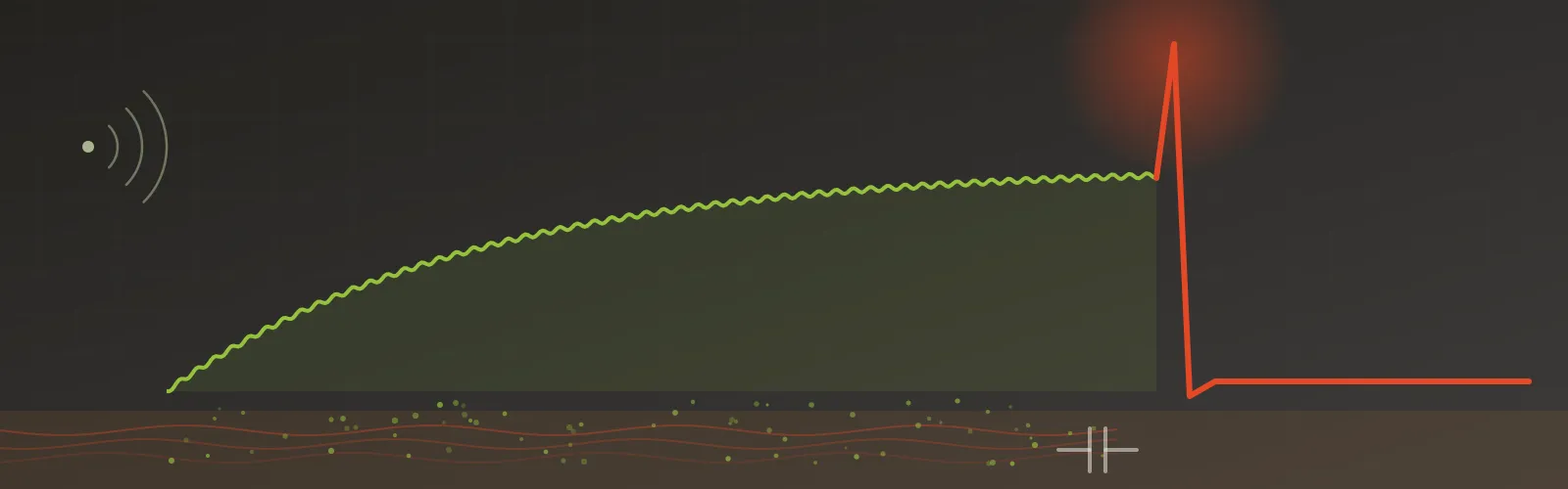
The system accumulates very small amounts of ambient power in a supercapacitor over a long period, then releases it as a high-current pulse within milliseconds when a fire is detected.
Two energy sources are envisaged:
- Thermoelectric generator (TEG): converts the temperature difference between a hot pipe or machine surface and the ambient air into electricity via the Seebeck effect.
- RF harvesting: collects Wi-Fi, cellular and industrial radio signals on site using an antenna and rectifier (rectenna) as a supplementary source.
The architecture has five layers:
- Energy harvesting: TEG and RF inputs.
- Power management (PMIC): boosts the millivolt-level input to a stable supply voltage.
- Storage: a 1–4.7 F main supercapacitor bank plus a diode-isolated reserve capacitor dedicated to firing.
- Control: a low-power microcontroller drawing nanoamps in deep sleep, with heat and smoke sensors and an external/manual trigger input.
- Load drivers: a MOSFET matrix for sequential pyrotechnic firing and an H-bridge for a latching valve.
Demand Side: How Much Energy Does Firing Take?
A single pyrotechnic ignition takes about 33 mJ; a valve pulse about 99 mJ. These are genuinely small numbers—and that is where the concept’s appeal comes from.
E = V × I × t
| Load | Current (A) | Voltage (V) | Duration (ms) | Energy (mJ) |
|---|---|---|---|---|
| Pyrotechnic initiator | 1.0 | 3.3 | 10 | 33 |
| Latching solenoid | 1.0 | 3.3 | 30 | 99 |
For comparison, a 1 F supercapacitor charged to 3.3 V holds about 5.4 J—enough for more than 160 ignitions. Storage capacity is not the problem. The problem is how the store gets filled, and whether it stays full.
Supply Side: How Fast Does the Store Fill, and How Long Does It Stay Full?
This is the weak link. The time to charge an empty capacitor depends directly on net harvested power, and that power can vary by a factor of thousands between installations.
E = ½ × C × V²
| Net harvested power | 33 mJ (one ignition) | 1 F full charge (5.4 J) | 4.7 F full charge (25.6 J) |
|---|---|---|---|
| 10 µW | ~55 min | ~6 days | ~30 days |
| 100 µW | ~5.5 min | ~15 hours | ~3 days |
| 1 mW | ~33 s | ~1.5 hours | ~7 hours |
Figures assume lossless conversion; in practice, PMIC efficiency and cold-start thresholds lengthen these times.
Rough orders of magnitude for each source (approximate, site-dependent):
- TEG: the literature reports volumetric power densities from 40 µW to 10 mW/cm³ for temperature differences of 5–20 °C [3]. With a sustained, meaningful ΔT and a heat sink, a few hundred µW to a few mW is achievable. With no ΔT, the output is zero.
- Ambient RF: measured power densities range from roughly 0.08 nW to 1 µW/cm² [3]; in-home measurements average below 1 nW/cm² [4]. Without a dedicated transmitter, this may stay below the rectifier’s operating threshold.
- Losses: supercapacitor leakage at room temperature is on the order of a few µA per farad and rises sharply with temperature [1]. That is a continuous loss of roughly 10 µW—far larger than the microcontroller’s nanoamp-level sleep current.
A rough example: with 5 µA of leakage, a 1 F capacitor drops from 3.3 V to 2 V in about 3 days; a 4.7 F capacitor in about 2 weeks. In other words, once harvesting stops, the system’s ready time is measured in days.
Weak Points and Open Questions
The obstacles to turning this concept into a safety product come not from physics but from reliability and cost.
- Readiness depends on the environment. During a plant shutdown, a weekend or winter maintenance, the ΔT disappears. After a few days the system may be empty exactly when it is needed. Is “ready if the environment allows” acceptable for a suppression trigger?
- Energy at the moment of fire is misleading. In a fire, the cold side and the surroundings heat up too; ΔT may collapse rather than grow. The design must rely on pre-stored energy, not on generation during the fire.
- The RF contribution is close to zero in practice. Given measured ambient RF densities [3], [4], this block adds cost and complexity but no meaningful energy unless a dedicated transmitter is present.
- “Magnetless” conflicts with a latching valve. The most common type of latching solenoid holds its plunger in place with a permanent magnet after a short coil pulse [5]. To keep the claim, a mechanically latched (bistable) valve or a motorized mechanism is required.
- Risk of unintended firing. Harvested supply rails rise slowly; the MCU may brown out and MOSFET gates may float. The design needs a dual-switch (high-side + low-side) firing path, gate pull-downs, a circuit that shorts the initiator when unarmed and a hardware interlock independent of the MCU.
- Temperature and lifetime. Supercapacitors are typically rated up to +65 °C; +85 °C is reachable only with voltage derating [2]. Next to a hot surface, lifetime shortens and leakage increases [1]. At 3.3 V, a diode drop of 0.3–0.7 V is also a significant loss, so low-ESR components are essential.
- Standards. In Europe, requirements for electrical automatic control and delay devices are set out in EN 12094-1. Although written for gas extinguishing systems [6], it is the natural reference point for any electronic unit that decides to release an extinguishing agent. On the detection side, the EN 54 series applies. How a device whose energy depends on its environment would pass such tests remains an open question.
- Cost. A TEG module, heat sink, ultra-low-voltage PMIC, low-ESR supercapacitor and safety circuitry together can easily cost more than a 10-year lithium battery and a simple circuit.
Where Could It Make Sense?
A purely batteryless trigger appears defensible only in narrow niches where a temperature difference is continuous and guaranteed:
- Continuously operating hot lines: steam and thermal oil pipes, the surroundings of furnaces and drying lines, process equipment running 24/7.
- Locations where battery replacement is very difficult or expensive: restricted-access points, areas requiring work permits, or locations inside ATEX zones.
A hybrid architecture may be the more realistic path: a long-life primary battery guarantees the firing energy, while energy harvesting takes over monitoring, reporting and extending battery life. The “batteryless” claim is dropped, but reliability is gained.
An Invitation to Discuss
Physics allows batteryless triggering; reliability and cost are not yet convincing. We want to settle this balance with the experience of people in the field:
- Does your site have fire-risk locations with a continuous, year-round temperature difference? Can you share measured ΔT values?
- For a suppression trigger, is battery replacement a real cost and operational problem for you, or a tolerable routine?
- Would you trust a safety device whose energy depends on its environment, provided it reports its own readiness status?
- In your view, is the right path a pure batteryless architecture, or a battery + energy-harvesting hybrid?
You can share your views with us through our contact page.
Sources
- Vishay, “How to Manage Leakage Current and Self-Discharge of EDLC Supercapacitors” (white paper).
- Eaton, “XT Supercapacitors – Snap-in Cylindrical Cells” (data sheet), 2018.
- “A Comprehensive Survey on RF Energy Harvesting: Applications and Performance Determinants”, University of West London Repository.
- Mimis et al., “Ambient RF energy harvesting trial in domestic settings”, IET Microwaves, Antennas & Propagation, 2015.
- TLX Technologies, “The Basics of Latching Solenoids”.
- BSI, “BS EN 12094-1:2003 – Electrical automatic control and delay devices”.